Canadian Customers: Take a look at our simplified Returns Process
Overview
To be used for as an aid for leg orthosis fabrication, suitable for the "structural orthosis fabrication" technique based on a drawing and for the lamination resin and vacuum-forming techniques based on a plaster cast
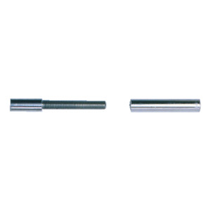
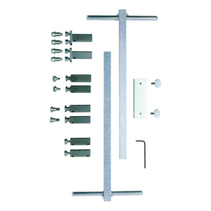
(a) 743Y55 alignment axis – Light metal –
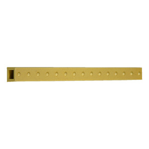
(b) 743Y70=80 parallel adapter, width 80 mm (standard) or 743Y70=50 parallel adapter, width 50 mm (accessory) – Light metal –
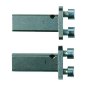
(c) 743Y56=1 alignment adapter, for gear segment bars – Stainless steel –
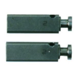
(d) 743Y56=2 alignment adapter with 12x7.6 pin flange – Stainless steel – and 501A1=12x7xM4 shoulder screw
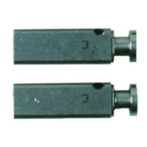
(e) 743Y56=3 alignment adapter with 14x9.6 pin flange – Stainless steel – and 501A1=14x9xM6 shoulder screw
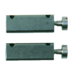
(f) ?743Y56=4 alignment adapter with M4 and M6 thread retainer? and 501A12=3 shoulder screw – Stainless steel –
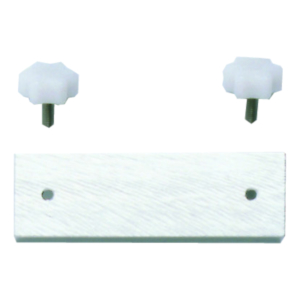
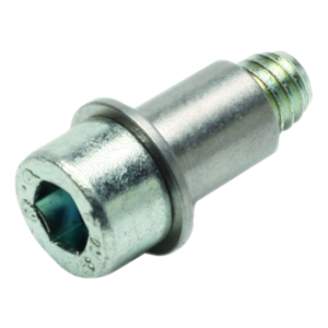
(g) 743Y72 Allen screw with collar
(h) 501A1=12x6xM4 shoulder screw for 743Y56=2 alignment adapter
(i) 501A1=12x8xM6 size 3 shoulder screw for alignment adapter
(j) 709S10=2.5 Allen key
(k) Shoulder screws: 30Y89, 30Y248=20, 30Y248=14-16, 30Y248=12
Specifications
| Article no. | Joint size | Adjustment adapter (size) | Shoulder screw |
|---|---|---|---|
| 17B105 | =16 | 2 | 501A1=10x7xM4 |
| 17B105 | =20 | 3 | 501A1=12x8xM6 |
| 17B106 | =16 | 2 | 501A1=10x7xM4 |
| 17B106 | =20 | 3 | 501A1=12x8xM6 |
| 17B20 | =16, =20 | 3 | 501A1=14x9xM6 |
| 17B21 | =16, =20 | 3 | 501A1=14x9xM6 |
| 17B23 | =16, =20 | 3 | 501A1=14x9xM6 |
| 17B26 | =16, =20 | 4 | 501A12=3 |
| 17B3 | =16, =20 | 4 | 501A12=3 |
| 17B33 | =16, =20 | 3 | 501A1=14x9xM6 |
| 17B43 | =16, =20 | 4 | 501A12=3 |
| 17B44 | =16, =20 | 4 | 501A12=3 |
| 17B45 | =16, =20 | 3 | 501A1=14x9xM6 |
| 17B46 | =16, =20 | 4 | 501A12=3 |
| 17B47 | =16, =20 | 4 | 501A12=3 |
| 17B53 | =16 | 2 | 501A1=12x7xM4 |
| 17B53 | =20 | 3 | 501A1=14x9xM6 |
| 17B54 | =16 | 2 | 501A1=12x7xM4 |
| 17B54 | =20 | 3 | 501A1=14x9xM6 |
| 17B57 | =16 | 2 | 501A1=12x7xM4 |
| 17B57 | =20 | 3 | 501A1=14x9xM6 |
| 17B59 | =16 | 2 | 501A1=12x7xM4 |
| 17B59 | =20 | 3 | 501A1=14x9xM6 |
| 17B62 | =16 | 2 | 501A1=12x7xM4 |
| 17B62 | =20 | 3 | 501A1=14x9xM6 |
| 17B63 | =16 | 2 | 501A1=12x7xM4 |
| 17B63 | =20 | 3 | 501A1=14x9xM6 |
| 17B71 | =16 =20 | 4 | 501A12=3 |
| 17B91 | =16, =20 | 3 | 501A1=14x9xM6 |
| 17B92 | =16, =20 | 3 | 501A1=14x9xM6 |
| 17B95 | =16 | 2 | 501A1=12x6xM4 |
| 17B95 | =20 | 3 | 501A1=12x8xM6 |
| 17B96 | =16 | 2 | 501A1=12x6xM4 |
| 17B96 | =20 | 3 | 501A1=12x8xM6 |
| 17B98 | =16 | 2 | 501A1=12x7xM4 |
| 17B98 | =20 | 3 | 501A1=14x9xM6 |
| 17F24 | =5, =4, =2 | 2 | 501A1=12x7xM4 |
| 17F34 | =6, =5 | 2 | 501A1=12x6xM4 |
| 17F46 | =6, =5 | 2 | 501A1=12x6xM4 |
| 17F47 | =6, =5 | 2 | 501A1=12x6xM4 |
| 17F53 | =6, =5 | 2 | 501A1=12x6xM4 |
| 17F63 | =6, =5, =4 | 2 | 501A1=12x6xM4 |
| 17F64 | =6, =5, =4 | 2 | 501A1=12x6xM4 |
| 17F65 | =6, =5 | 2 | 501A1=12x6xM4 |
| 17K29 | =4 | 3 | 501A1=14x9xM6 |
| 17K29 | =6, =5 | 2 | 501A1=12x6xM4 |
| 17K32 | =4 | 3 | 501A1=14x9xM6 |
| 17K32 | =6, =5 | 2 | 501A1=12x6xM4 |
| 17K33 | =4 | 3 | 501A1=14x9xM6 |
| 17K33 | =6, =5 | 2 | 501A1=12x6xM4 |
| 17K34 | =4 | 3 | 501A1=14x9xM6 |
| 17K34 | =6, =5 | 2 | 501A1=12x6xM4 |
| 17K42 | =4 | 3 | 501A1=14x9xM6 |
| 17K42 | =6, =5 | 2 | 501A1=12x6xM4 |
| 17K43 | 1 | ||
| 17K45 | 1 | ||
| 17K46 | 1 | ||
| 17K47 | 1 | ||
| 17LK3 | =12 =14 =16 =20 | 4 | 30Y89 |
| 7U56 | 1 |
Spare parts
Documents
743R6 Alignment Fixture - Instructions for Use (User / Technician)
Instructions for Use
PDF Document | Published: Sep 25, 2013

